Sections of the site
Editor's Choice:
- Genetic maps of chromosomes"
- Fumigation of a wooden house against beetles with phosphine
- Visible light spectrum. Visible range. Visible light is an electromagnetic wave
- Hydrogen: distribution in nature
- Interaction of parallel currents figure
- 4 internal friction in liquids
- “About the world of the dead” - T. Tikhoplav. Vitaly and Tatyana Tikhoplav Where did Tatyana Tikhoplav disappear from contact?
- Why does the Moon only attract water?
- Geography What you need to take with you
- How teachers are certified Compliance with the position held for biology teachers
Advertising
|
Ampere power A current-carrying conductor in a magnetic field experiences a force equal to F = I·L·B·sina I is the current strength in the conductor; B - module of the magnetic field induction vector; L is the length of the conductor located in the magnetic field; a is the angle between the magnetic field vector and the direction of the current in the conductor. The force acting on a current-carrying conductor in a magnetic field is called the Ampere force. The maximum ampere force is: It corresponds to a = 900. The direction of the Ampere force is determined by the left hand rule: if the left hand is positioned so that the perpendicular component of the magnetic induction vector B enters the palm, and four extended fingers are directed in the direction of the current, then the thumb bent 90 degrees will show the direction of the force acting on the segment conductor with current, that is, Ampere force.
During the experiment, we observed a force that cannot be explained within the framework of electrostatics. When two parallel conductors carry current in only one direction, there is an attractive force between them. When currents flow in opposite directions, the wires repel each other. The actual value of this force acting between parallel currents, and its dependence on the distance between the wires, can be measured using a simple device in the form of a scale. In view of the absence of such, we will take on faith the experimental results that show that this force is inversely proportional to the distance between the axes of the wires: F (1/r). Since this force must be due to some influence spreading from one wire to another, such a cylindrical geometry will create a force that depends inversely on the first power of the distance. Let us remember that the electrostatic field propagates from a charged wire also with a distance dependence of the form 1/r. Based on experiments, it is also clear that the strength of interaction between the wires depends on the product of the currents flowing through them. From symmetry we can conclude that if this force is proportional to I1, it must be proportional to I2. That this force is directly proportional to each of the currents is simply an experimental fact. By adding a proportionality coefficient, we can now write down the formula for the force of interaction between two parallel wires: F (l/r, F (I1 I2); therefore, The proportionality factor will contain the factor 2( associated with it, not the constant itself. The interaction between two parallel wires is expressed as force per unit length. The longer the wires, the greater the power: The distance r between the axes of the wires F/l is measured in meters. Force per 1 meter of length is measured in newtons per meter, and currents I1 I2 - in amperes. In a school physics course, the coulomb is first defined in terms of ampere, without giving the definition of ampere, and then the value of the constant appearing in Coulomb's law is taken on faith. Only now is it possible to move on to consider the definition of ampere. When the equation for F/l is assumed to determine the ampere. The constant is called the magnetic constant. It is similar to the constant 0 - the electrical constant. However, there is an operational difference in assigning values to these two constants. We can choose any arbitrary value for any one of them. But then the second constant must be determined experimentally, since the coulomb and ampere are related. Based now on the formula described above, the value of an ampere can be expressed in words: if the interaction per 1 m of length of two long parallel wires located at a distance of 1 m from each other is equal to 2 * 10-7 N, then the current in each wire is 1A. In the case where the interacting wires are perpendicular to each other, there is only a very small area of influence where the wires pass close to each other, and therefore the interaction force between the wires can be expected to be small. In fact, this force is zero. Since the force can be considered positive when the currents are parallel, and negative when the currents are antiparallel, it is plausible that this force should be zero when the wires are perpendicular, for this zero value lies midway between the positive and negative values. The SI unit is 1 Ampere (A) = 1 Coulomb/second. To measure current, a special device is used - an ammeter (for devices designed to measure small currents, the names milliammeter, microammeter, galvanometer are also used). It is included in the open circuit in the place where the current strength needs to be measured. The main methods for measuring current strength are: magnetoelectric, electromagnetic and indirect (by measuring voltage at a known resistance with a voltmeter). Relativistic form of Coulomb's law: Lorentz force and Maxwell's equations. Electromagnetic field. Coulomb's law:
Maxwell's equations: is a system of differential equations that describe the electromagnetic field and its relationship with electric charges and currents in vacuum and continuous media.
Electromagnetic field: is a fundamental physical field that interacts with electrically charged bodies, representing a combination of electric and magnetic fields that can, under certain conditions, generate each other. Stationary magnetic field. Magnetic field induction, superposition principle. Bio-Savart's Law. Constant (or stationary) magnetic field: is a magnetic field that does not change over time. M\G is a special type of matter through which interaction occurs between moving electrically charged particles. Magnetic induction: - vector quantity, which is the force characteristic of the magnetic field at a given point in space. Determines the force with which the magnetic field acts on a charge moving at speed . Superposition principle:- In its simplest formulation, the principle of superposition states: the result of the influence of several external forces on a particle is the vector sum of the influence of these forces.
Ampere power. Interaction of parallel conductors with current. The work of magnetic field forces to move a coil with current. One of the manifestations of a magnetic field is its forceful effect on a current-carrying conductor placed in a magnetic field. Ampere established that a current-carrying conductor placed in a uniform magnetic field whose induction is acted upon by a force proportional to the current strength and the magnetic field induction: F = IBℓsinα (15.22) [α is the angle between the direction of the current in the conductor and the magnetic field induction]. This formula turns out to be valid for a straight conductor and a uniform field. If the conductor has an arbitrary shape and the field is inhomogeneous, then expression (3.125) takes the form dF = IBdℓsinα (15.23) or in vector form
The product Idℓ is called the current element. Relations (15.23), (15.24) express Ampere's law.
This force is always perpendicular to the plane in which the conductor and the vector lie. Knowing the direction and magnitude of the force acting on any section dℓ of the conductor, we can calculate the force acting on the entire conductor. To do this, you need to find the sum of the forces acting on all conductor sections: Using Ampere's law, consider interaction of parallel conductors with current (Fig. 15.11). Let us assume that in a homogeneous isotropic medium, the relative magnetic permeability of which is μ, two conductors are located at a distance d from each other. Let the current I 1 flow through one of them and the other - I 2 in the water direction.
dF i = B 1 I 2 dℓ i [ The vector is directed perpendicular to the direction of current I, therefore sinα=1. Taking this into account, we find
Using the left hand rule, we determine the direction of this force. To determine the force F 12, i.e. the force acting from conductor 1 on conductor 2, you need to sum up all the elementary forces dF i The force with which two conductors interact is proportional to the product of the currents flowing through the conductors and inversely proportional to the distance between them. If currents flow through conductors in the same directions, then conductors attract, and in opposite directions they repel. Ampere's law is fundamental in the doctrine of magnetism and plays the same role as Coulomb's law in electrostatics. 15.5 Circuit with current in a magnetic field. Work on moving a conductor and a current-carrying circuit in a magnetic field
(Fig. 15.12). An Ampere force acts on each side of the circuit. Forces act on the horizontal sides ℓ of the contour that stretch or compress) the contour without rotating it. Each of the vertical sides a is acted upon by a force F = IBa. These forces create a couple of forces, the moment of which M = Fℓcosφ (15.27) [φ is the angle between the vector and the side of the contour ℓ. The moment of force tends to rotate the contour so that the flow F penetrating the contour is maximum. Substituting the expression for force into formula (15.27), we have М = IBaℓcosφ= ISBcosφ= p m Bcos(π/2-α)= = p m B sinα (15.28) The quantity IS is called magnetic moment of the circuit p m.. Vector p m coincides with the direction of the positive normal to the contour plane. Mechanical moment M, acting on a circuit with current in a uniform magnetic field is proportional to the magnetic moment p m of the circuit, the induction B of the magnetic field and the sine of the angle between the direction of the vectors p m (normal to the circuit) and . In vector form, relation (15.28) has the form M = (15.29)
Under the influence of this force, the conductor will move parallel to itself for a segment from position 1 to position 2. The work done by the magnetic field is equal to dA=Fdx=IBℓdx=IBdS=IdФ, (15.30) since ℓdx = dS is the area crossed by the conductor when it moves in a magnetic field, VdS = dФ is the flux of the magnetic induction vector penetrating this area. Thus, dA= IdФ, (15.31) those. the work done to move a current-carrying conductor in a magnetic field is equal to the product of the current strength and the magnetic flux crossed by the moving conductor. Work on moving a conductor with current I from point 1 to point 2 is determined by the formula:
The work of moving a closed loop with current in a magnetic field is also determined by the formula. The formula remains valid for a circuit of any shape in an arbitrary magnetic field. § 15.5. Lorentz force. Motion of a particle in a magnetic field. Hall effect Moving electric charges create a magnetic field around themselves, which propagates in a vacuum at the speed of light. When a charge moves in an external magnetic field, a force interaction of magnetic fields occurs, determined by Ampere’s law. The process of interaction of magnetic fields was studied by Lorentz, who derived a formula for calculating the force exerted by a magnetic field on a moving charged particle. Lorentz is the creator of classical electronic theory. His works in the fields of electrodynamics, thermodynamics, static mechanics, optics, radiation theory, and atomic physics are widely known. For his studies of the influence of magnetism on radiation processes, he was awarded the Nobel Prize in 1902. The force exerted by a magnetic field on a moving charge is called Lorentz force And , is equal F l = qυВ sinα (15.33) where q is the particle charge; - particle speed; B is the magnetic field induction, α is the angle between the direction of the particle velocity and the magnetic induction vector . This force is perpendicular to the vectors and. The direction of the Lorentz force is determined according to the left hand rule: if you position your left palm so that the four outstretched fingers indicate the direction of movement of the positive charge, and the magnetic field vector enters the palm, then the outstretched thumb will show the direction of the Lorentz force acting on this charge. With a change in the sign of the charge, the direction of the force changes to the opposite. Analyzing expression (3.146), we can draw the following conclusions: 1. If charge speed =0; F l =0. A magnetic field does not act on a stationary particle. 2. If a particle flies into a magnetic field parallel to its lines of force. α=0°, sin0°=0; F l =0. A magnetic field does not act on a stationary charged particle; The particle will continue to move uniformly and in a straight line at the same speed that it had. 3. If the particle flies in perpendicular to the magnetic field lines ┴ . α=90°, sin90°=1; F l =qυV. The Lorentz force bends the trajectory of motion, acting as a centripetal force.
The greater the speed of a particle, the larger the radius of the circle along which it moves, but the period of revolution does not depend on either the speed or the radius of the circle.
4. If a particle moves at an angle β to the lines, then the trajectory of the particle will be a helical line (spiral) enclosing the magnetic field lines (Fig. 3.60).
In 1892, Lorentz obtained a formula for the force with which an electromagnetic field acts on any charged particle located in it:
This force is called electromagnetic Lorentz force , and this expression is one of the basic laws of classical electrodynamics. When an electric charge moves simultaneously in electric and magnetic fields, the resulting force acting on the particle is equal to F = qυВsinα+ qE (15.38) In this case, the force has two components: from the influence of magnetic and electric fields. There is a fundamental difference between these components. An electric field changes the velocity and, consequently, the kinetic energy of a particle; a uniform magnetic field changes only the direction of its movement. Hall effect The American scientist E. Hall discovered that in a conductor placed in a magnetic field, a potential difference (transverse) arises in the direction perpendicular to the magnetic induction vector B and current I, due to the action of the Lorentz force on charges moving in this conductor (Fig. 3.62) . Experience shows that the transverse potential difference is proportional to the current density j, magnetic induction and distance d between the electrodes:
Therefore, the transverse potential difference is equal to Average speed υ electrons can be expressed in terms of current density j, since j=ne υ , That's why Equating this expression to formula (15.39), we obtain . The Hall constant depends on the electron concentration. Based on the measured value of the Hall constant, it is possible to: 1) determine the concentration of current carriers in the conductor (with the nature of conductivity and charge of carriers known); 2) judge the nature of the conductivity of semiconductors, since the sign of the Hall constant coincides with the sign of the charge of current carriers. Used for multiplying direct currents in analog computers, in measuring technology (Hall sensor Examples of problem solving Example.A rectangular frame with sides a = 5 cm and b = 10 cm, consisting of N = 20 turns, is placed in an external uniform magnetic field with induction B = 0.2 Tesla. The normal to the frame makes an angle with the direction of the magnetic field. Determine the torque acting on the frame if a current I=2A flows through it. Given: a= 5cm=0.05m; b=10cm=0.1m; N=20; B=0.2 T; . ; I=2A. Find: M. Solution.The mechanical torque acting on a current-carrying frame placed in a uniform magnetic field is
- magnetic moment of the frame with current. Module M=p m Bsinα. Since the frame consists of N turns, then M=Np m Bsinα (1) where is the magnetic moment of the frame with current p m =IS=I a b. (2) Substituting formula (2) into expression (1), we find the required torque M=NIB a bsinα. Answer: M=0.02 N∙m Example.Current flows through a thin wire ring. Determine how many times the induction in the center of the circuit will change if the conductor is given the shape of a square without changing the current strength in the conductor. Solution. The vector in the center of the circular current is directed at the selected direction of the current (see figure), according to the rule of the right screw, perpendicular to us in the drawing (in the figure this is indicated by a dot in a circle). Its module where I is the current strength; R is the radius of the ring; μ 0 - magnetic constant; μ is the magnetic permeability of the medium.
From formulas (1) and (2) we obtain the relation Answer: Example.Two infinitely long straight parallel conductors located in a vacuum at a distance of R = 30 cm carry identical currents in the same direction. Determine the magnetic induction B of the field created by the currents at point A, lying on the straight line connecting the conductors and lying at a distance r=20cm to the right of the right wire (see figure). The current strength in the conductors is 20A. Given:μ=1; R=30cm=0.3m; r=20cm=0.2m; I 1 = I 2 =I=20 A. Find:B. Solution. Let the currents be directed perpendicular to the drawing plane from According to the principle of superposition, the magnetic induction of the resulting field at point A where and is the magnetic induction of fields at this point created by the first and second conductors. Vectors and and are codirectional, so the addition of vectors can be replaced by the addition of their modules B=B 1 +B 2. (1) Magnetic induction of fields created by infinitely long straight conductors with current I 1 and I 2,
where μ 0 – magnetic constant; μ is the magnetic permeability of the medium. Substituting expression (2) into formula (1) and taking into account that I 1 =I 2 =I and μ=1 (for vacuum), we obtain the desired expression for magnetic induction at point A:
Answer: V=28 µT. Example.Through two infinitely long straight parallel conductors located in a vacuum, the distance between which is d=15cm, currents I 1 =70A and I 2 =50A flow in one direction. Determine the magnetic induction B of the field at point A, located at a distance of r 1 = 10 cm from the first and r 1 = 20 cm from the second conductor. Given:μ=1; d=15cm=0.15 m; I 1 =70A; I 2 =50A; r 1 =10cm=0.1m; r 2 =20cm=0.2m. Find:B. Solution. Let the currents be directed perpendicular to the drawing plane towards us. The magnetic induction vectors are directed tangentially to the magnetic induction lines. According to the principle of superposition, magnetic induction at point A (see figure)
Substituting these expressions into formula (1), we find the required B:
Answer: V=178 µT. Example.In the same plane with an infinitely straight current-carrying conductor I = 10 A there is a rectangular wire frame (side a = 25 cm, b = 10 cm), through which current I 1 = 2 A flows. The long sides of the frame are parallel to the forward current, and the nearest of them is located from the forward current at a distance of c = 10 cm and the current in it is codirectional to the current I. Determine the forces acting on each side of the frame. Given:I=10A; a=25cm=0.25m; b=10 cm=0.10 m;; I 1 =2 A; c=10cm=0.1m. Find: F 1 ; F 2 ; F 3; F 4;
(we consider the case of vacuum), where r is the distance from the direct current to the point in question. The force with which the direct current field acts can be found by summing up the elementary forces determined by Ampere's law, The vector within the frame is directed perpendicular to its plane beyond the drawing, and within each side the angle is . This means that within one side the elementary forces are parallel to each other and the addition of vectors Can be replaced by adding their modules:
where integration is carried out over the corresponding side of the frame The short sides of the frame are located equally relative to the wire, and therefore the forces acting on them are numerically equal, but oppositely directed. Their direction, as well as the direction of other forces (see figure), is determined by the left-hand rule. Along each of the short sides of the rectangle, the magnetic induction changes [see. formula (1)]. Then, after performing the integration [taking into account (2)],
The long sides of the frame are parallel to the forward current, being at distances c and c+b from it, respectively. Then
where and Answer: F 1 =10 µN; F 2 =2.77 µN; F 3 =5 μN; F 4 =2.77 µN. Example.An electron that has passed through an accelerating potential difference U=1 kV flies into a uniform magnetic field with induction B=3mT perpendicular to the magnetic induction lines. Determine: 1) the force acting on the electron; 2) the radius of the circle along which the electron moves; 3) the period of revolution of the electron. Given: m=9.11∙10 -31 kg; e=1.6∙10 -19 C; U=1kV=1∙10 3 V; B=3mT=3∙10 -3 T; α=90º. Find: 1)F; 2) R; 3) T. Solution. When an electron moves in a magnetic field with a speed v, it is acted upon by the Lorentz force F l =eυBsinα, where α is the angle between vectors and (in our case α=90º). Then When passing through an accelerating potential difference, the work of the electrostatic field forces goes to impart kinetic energy to the electron, Substituting expression (2) into formula (1), we find the desired force acting on the electron,
It is known from mechanics that a constant force perpendicular to the speed, and this is the Lorentz force (1), causes motion in a circle. It imparts normal acceleration to the electron, where R is the radius of the circle. According to Newton's second law, F=ma, where F=eυB. Then where does the desired radius of the circle take into account (2) Electron orbital period Substituting expressions (3) and (2) into formula (4), we find the required electron circulation period Answer: 1)F=9∙10 -15 N; 2) R=3.56 cm; 3) T=11.9 ns. Example.A proton, having a speed of υ = 10 4 m/s, flies into a uniform magnetic field with induction B = 10 mT at an angle α = 60º to the direction of the magnetic induction lines. Determine the radius R and pitch h of the helix along which the proton will move. Given: υ=10 4 m/s; e=1.6∙10 -19 C; m=1.67∙10 -27 kg; B=10mT=10∙10 -3 T; α=60º. Find:R; h. Solution. The movement of a proton in a uniform magnetic field with a speed directed at an angle α to the vector occurs along a helical line (see figure). To prove this, let us decompose the velocity vector into components parallel (υ x =υcosα) and perpendicular (υ y =υsinα) to the induction vector.
The Lorentz force imparts normal acceleration to the proton (R is the radius of the circle). According to Newton's second law, F=m a n, where F l =eυ y B – Lorentz force. Then Where does the desired radius of the helical line along which the proton will move come from?
The pitch of the helix is equal to the distance traveled by the proton along the x axis during one full revolution, i.e. h=υ x T= υTcosα, (1) where is the rotation period
Substituting formula (2) into expression (1), we find the desired pitch of the helix Answer: R=9.04mm; h=3.28 cm. Example.A uniform magnetic field with a strength of H=2kA/m is created between the plates of a flat capacitor located in a vacuum. The electron moves in the capacitor parallel to the capacitor plates and perpendicular to the direction of the magnetic field at a speed of υ=2 Mm/s. Determine the voltage U applied to the capacitor if the distance d between its plates is 1.99 cm. Given: μ=1; N=2kA/m=2∙10 3 A/m; υ=2Mm/s=2∙10 6 m/s; d=1.99 cm=1.99∙10 -2 m). Find:U.
Formula expressing the relationship between magnetic induction and magnetic field strength For the case of vacuum (μ=1) it has the form B=μ 0 N. Substituting this formula into expression (1), we find the desired voltage on the capacitor plates Answer: U=100B. Example.A current I = 5 A is passed through a cross-section of a copper plate (copper density ρ = 8.93 g/cm 3) with a thickness of d = 0.1 mm. The plate with the current is placed in a uniform magnetic field with induction B = 0.5 T, perpendicular to the direction current and the edge of the plate. Determine the transverse (Hall) potential difference arising in the plate if the concentration of n free electrons is equal to the concentration of n" conductor atoms. Given: ρ=8.93 g/cm 3 =8.93∙10 3 kg/m 3 ; d=0.1mm=1∙10 -4 m; I=5A; B=0.5 T; n = n" ; M=63.5∙10 -3 kg/mol. Find:Δφ.. Solution. The figure shows a metal plate with current density in a magnetic field perpendicular (as in the problem statement). In this direction, the speed of current carriers in metals - electrons - is directed from right to left. The electrons experience the Lorentz force, which in this case is directed upward. At the upper edge of the plate there is an increased concentration of electrons (it will be charged negatively), and at the lower edge there is a lack of electrons (it will be charged positively). Therefore, an additional transverse electric field appears between the edges of the plate, directed from bottom to top. In the case of a stationary distribution of charges in the transverse direction (the strength E B of the transverse field will reach such a value that its action on the charges will balance the Lorentz force)
Where A– width of the plate; Δφ - transverse (Hall) potential difference. Current strength I=jS=neυS=neυ a d, (2) where S is the cross-sectional area of the plate with thickness d; n - electron concentration; υ is the average speed of ordered movement of electrons. Substituting (2) into (1), we get According to the conditions of the problem, the concentration of free electrons is equal to the concentration of conductor atoms. Hence,
where N A =6.02∙10 23 mol -1 – Avogadro’s constant; V m - molar volume of copper; M – molar mass of copper; ρ is its density. Substituting formula (4) into expression (3), we find the desired Example.Magnetic induction B on the axis of a toroid without a core (external diameter of the toroid d 1 = 60 cm, internal diameter d 2 = 40 cm), containing N = 200 turns, is 0.16 mT. Using the vector circulation theorem, determine the current strength in the toroid winding. Given: d 1 =60 cm=0.6 m; d 2 =40 cm=0.4 m; N=200; B=0.16 mT=0.16∙10 -3 T. Find: I. Solution. Vector circulation
those. equal to the algebraic sum of the currents covered by the circuit along which the circulation is calculated, multiplied by the magnetic constant. As a contour, we choose a circle located in the same way as the magnetic induction line, i.e. a circle of some radius r, the center of which lies on the axis toroid. From the symmetry condition it follows that the modulus of the vector at all points of the magnetic induction line is the same, and therefore expression (1) can be written in the form
(take into account that the current strength in all turns is the same, and the circuit covers a number of currents equal to the number of turns of the toroid). For the center line of the toroid). For the centerline of a toroid. Substituting r into (2), we obtain the required current strength:
Answer: I=1 A Example.In the same plane with an infinite straight wire through which a current I = 10A flows, there is a square frame with side a = 15 cm. Determine the magnetic flux Ф penetrating the frame if the two sides of the frame are parallel to the wire, and the distance d from the wire to the nearest side of the frame is 2 cm. Given: I=10A; a=15 cm=0.15 m; d=2 cm=0.02m. Find: F.
The square frame is in a non-uniform direct current field with induction (we consider the case of vacuum), where x is the distance from the wire to the point in question. The magnetic field is created by direct current (the direction is shown in the figure), and the vector is perpendicular to the plane of the frame (directed perpendicular to the drawing from us, which is shown in the figure by crosses), therefore for all points of the frame B n = B. We divide the frame area into narrow elementary areas of width dx and area a dx (see figure), within which the magnetic induction can be considered constant. Then the flow through the elementary platform
By integrating expression (1) in the range from to, we find the desired magnetic flux
Answer: Ф=0.25 µWb Example.A circular conducting circuit with a radius of r=6cm and a current I=2A is established in a magnetic field so that the plane of the circuit is perpendicular to the direction of a uniform magnetic field with induction B=10mT. Determine the work that must be done to slowly rotate the contour at an angle relative to the axis that coincides with the diameter of the contour. Given: r=6 cm=0.06 m; I=2 A; B=10 mT=10∙10 -3 T; . Find: A ext. Solution. Work done by field forces to move a closed conductor with current I A=I(F 2 -F 1), (1)
Flux of magnetic induction through a flat circuit of area S in a uniform magnetic field with induction B where α is the angle between the normal vector to the contour surface and the magnetic induction vector. In the initial position, Fig. a, circuit (the circuit is established freely), the flux of magnetic induction is maximum (α=0; cosα=1) and Ф 1 =BS (S-circuit area), and in the final position, Fig. b (; cosα=0), Ф 2 =0. Then, substituting these expressions into formula (1), we find that (take into account that the area of the circular contour is S=πr 2). The work of external forces is directed against the field forces (equal to it in magnitude, but opposite in sign), therefore the required work A in =πIBr 2 . Answer: A vn=226 µJ. The force of interaction between current elements, proportional to the currents and the length of the elements, inversely proportional to the square of the distance between them and depending on their relative positionAnimation Description In 1820, Ampere discovered the interaction of currents - the attraction or repulsion of parallel currents. This made it possible to set the research task: to reduce all magnetic interactions to the interaction of current elements and to find the law of their interaction as a fundamental law that plays a role in magnetism similar to Coulomb’s law in electricity. The currently used formula for the interaction of current elements was obtained in 1844 by Grassmann (1809-1877) and has the form:
where d F 12 is the force with which the current element I 1 d I 1 acts on the current element I 2 d I 2 ; r 12 - radius vector drawn from the element I 1 d I 1 to the current element I 2 d I 2 ; c =3H 108 m/s - the speed of light. Interaction of current elements
Rice. 1 The force d F 12 with which the current element I 2 d I 2 acts on the current element I 1 d I 1 has the form:
The forces d F 12 and d F 21, generally speaking, are not collinear to each other, therefore, the interaction of current elements does not satisfy Newton’s third law: d F 12 + d F 21 No. 0. Law (1) has an auxiliary meaning, leading to correct, experimentally confirmed force values only after integrating (1) over the closed contours L 1 and L 2. The force with which the current I 1 flowing through the closed circuit L 1 acts on the closed circuit L 2 with the current I 2 is equal to:
The force d F 21 has a similar form. For the forces of interaction of closed circuits with current, Newton’s third law is satisfied: dF 12 +d F 21 =0 In complete analogy with electrostatics, the interaction of current elements is represented as follows: the current element I 1 d I 1 at the location of the current element I 2 d I 2 creates a magnetic field, the interaction with which the current element I 2 d I 2 leads to the emergence of a force d F 12.
Relationship (5), which describes the generation of a magnetic field by a current, is called the Biot-Savart law. The force of interaction between parallel currents. The induction of the magnetic field created by a straight-line current I 1 flowing along an infinitely long conductor at the point where the current element I 2 dx 2 is located (see Fig. 2) is expressed by the formula: . (in "SI") (6) Interaction of two parallel currents
Rice. 2 Ampere's formula, which determines the force acting on a current element I 2 dx 2 located in a magnetic field B 12, has the form:
This force is directed perpendicular to the conductor with current I 2 and is an attractive force. A similar force is directed perpendicular to the conductor with current I 1 and is an attractive force. If currents in parallel conductors flow in opposite directions, then such conductors repel. André Marie Ampère (1775-1836) - French physicist. Timing characteristics Initiation time (log to -15 to -12); Lifetime (log tc from 13 to 15); Degradation time (log td from -15 to -12); Time of optimal development (log tk from -12 to 3). Diagram:
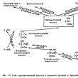
Technical implementations of the effect Installation diagram for “weighing” measurement currents Implementation of a 1A unit using a force acting on a current-carrying coil. Inside a large fixed coil is a “measurement coil” that is subjected to the force to be measured. The measuring coil is suspended from the beam of a sensitive analytical balance (Fig. 3). Installation diagram for “weighing” measurement currents
Rice. 3 Applying an effect Ampere's law of interaction of currents, or, which is the same thing, magnetic fields generated by these currents, is used to design a very common type of electrical measuring instruments - magnetoelectric devices. They have a light frame with wire, mounted on an elastic suspension of one design or another, capable of rotating in a magnetic field. The ancestor of all magnetoelectric devices is the Weber electrodynamometer (Fig. 4). Weber electrodynamometer
Rice. 4 It was this device that made it possible to conduct classical studies of Ampere's law. Inside the fixed coil U, a moving coil C, supported by a fork ll, hangs on a bifilar suspension, the axis of which is perpendicular to the axis of the fixed coil. When current passes sequentially through the coils, the moving coil tends to become parallel to the stationary one and rotates, twisting the bifilar suspension. The rotation angles are measured using a mirror f attached to the frame ll ў. Literature 1. Matveev A.N. Electricity and magnetism. - M.: Higher School, 1983. 2. Tamm I.E. Fundamentals of the theory of electricity. - M.: State Publishing House of Technical and Theoretical Literature, 1954. 3. Kalashnikov S.G. Electricity. - M.: Nauka, 1977. 4. Sivukhin D.V. General course of physics. - M.: Nauka, 1977. - T.3. Electricity. 5. Kamke D., Kremer K. Physical foundations of units of measurement. - M.: Mir, 1980. Keywords
Sections of natural sciences: Experience shows that electric currents interact with each other. For example, two thin straight parallel conductors carrying currents (we will call them direct currents) attract each other if the currents in them have the same direction, and repel each other if the currents are opposite. The interaction force per unit length of each of the parallel conductors is proportional to the magnitude of the currents in them and inversely proportional to the distance b between them:
For reasons that will become clear later, we denoted the proportionality coefficient by . The law of interaction of currents was established in 1820 by Ampere. A general expression of this law, suitable for conductors of any shape, will be given in § 44. Based on relation (39.1), the unit of current is established in the SI and in the absolute electromagnetic system of units (SGSM system). The SI unit of current, the ampere, is defined as the strength of a constant current which, passing through two parallel straight conductors of infinite length and negligible circular cross-section, located at a distance of 1 m from each other in a vacuum, would produce between these conductors a force equal to N for every meter of length. A unit of charge, called a coulomb, is defined as the charge passing in 1 s through the cross-section of a conductor through which a direct current of 1 A flows. In accordance with this, the coulomb is also called an ampere-second (A s). In rationalized form, formula (39.1) is written as follows:
where is the so-called magnetic constant (cf. formula (4.1)). To find the numerical value, we will use the fact that, according to the definition of ampere, the force is equal. Substitute these values into formula (39.2):
The coefficient k in formula (39.1) can be made equal to unity by choosing the current unit. This is how the absolute electromagnetic unit of current strength (SGSM-unit of current strength) is established, which is defined as the strength of such a current that, flowing through a thin straight infinitely long wire, acts on an equal and parallel direct current, separated by 1 cm, with a force of 2 din for every centimeter of length. In the SGSE system, k turns out to be a dimensional quantity different from unity. According to formula (39.1), the dimension k is determined by the following expression:
We took into account that the dimension is the dimension of force divided by the dimension of length; therefore the dimension of the product is equal to the dimension of the force. According to formulas (3.2) and (31.7)
Substituting these values into expression (39.4), we find that Therefore, in the SGSE system k can be represented in the form where c is a quantity having the dimension of speed, called the electrodynamic constant. To find its numerical value, we use the relationship (3.3) between the coulomb and the SGSE unit of charge, which was established experimentally. The force in is equivalent to . According to formula (39.1), currents interact with such force in SGSE units (i.e. 1 A) each in the manner
The value of the electrodynamic constant coincides with the speed of the scotch in vacuum. Maxwell's theories imply the existence of electromagnetic waves, the speed of which in vacuum is equal to the electrodynamic constant c. The coincidence with the speed of light in a vacuum gave Maxwell reason to assume that light is an electromagnetic wave. The value of k in formula (39.1) is equal to 1 in the SGSM system and in the SGSE system. It follows that a current of 1 SGSE unit is equivalent to a current of 3-10° SGSE units: Multiplying this ratio by 1 s, we get |

 Lorentz force:
  LORENTZ FORCE - a force acting on a charged particle moving in an electromagnetic field. If the left hand is positioned so that the component of magnetic induction B, perpendicular to the speed of the charge, enters the palm, and the four fingers are directed along the movement of the positive charge (against the movement of the negative), then the thumb bent 90 degrees will show the direction of the Lorentz force acting on the charge.

 To determine the direction of the force acting on a current-carrying conductor placed in a magnetic field, it is used left hand rule: if the left hand is positioned so that the lines of magnetic induction enter the palm, and the extended four fingers coincide with the direction of the current in the conductor, then the bent thumb will indicate the direction of the force acting on the current-carrying conductor placed in a magnetic field(Fig. 15.10) .
 Select element dℓ 2 on conductor 2. This element will be acted upon by the Ampere force
 - induction of the magnetic field created by the first conductor at the location of the second conductor].
 (15.25)
 A current-carrying circuit with sides a and ℓ is placed in a magnetic field
 Consider a conductor of length ℓ with current I, placed in a uniform external magnetic field perpendicular to the plane of the circuit and which can move freely in this field under the action of the Ampere force (Fig. 15.13).
 (15.32)
 It is very important to use this phenomenon in the study of cosmic particles to determine the sign of the charge. The entry of a flying particle into a magnetic field causes a change in its trajectory depending on the sign of the charge (Fig. 3.59). In Fig. 3.59, the magnetic field induction vector is directed perpendicular to the plane of the drawing (away from us). The particle will move in a circle, the radius R of which can be determined from the equality of the centripetal force and the Lorentz force:
 (15.36)
 The pitch h of the spiral is determined by υ t - the tangential component of the velocity υ of the particle. The radius of the spiral depends on υ n - the normal component of velocity υ.
 Let us assume that electrons move with an ordered average speed υ and each electron is acted upon by a Lorentz force equal to eBυ. Under its action, the electrons are displaced so that one of the faces of the sample will be charged negatively, the other - positively, and an electric field will arise inside the sample, i.e. υ B = eE.
 ,
, The side of the square inscribed in the ring is equal to (the circumference of the ring is 2πR). The vector in the center of the square is also directed perpendicular to the drawing towards us. The magnetic induction at the center of the square is equal to the sum of the magnetic inductions created by each side of the square. Then the module, according to the Biot-Savart-Laplace law,
 us, which is indicated by crosses in the figure. Magnetic induction lines are closed and surround conductors with currents. Their direction is determined by the right screw rule. The vector at each point is directed tangentially to the magnetic induction line (see figure).
 where and are, respectively, the magnetic induction fields created by current-carrying conductors I 1 and I 2(directions of vectors and currents I 1 and I 2 shown in the figure). The modulus of the vector according to the cosine theorem,
 .
. Solution.
A rectangular frame is in a non-uniform direct current field with induction
Solution.
A rectangular frame is in a non-uniform direct current field with induction (2)
(2) .
. ;
; ,
, Movement in the direction of the field occurs with a uniform speed υ x, and in the direction perpendicular to the vector, under the influence of the Lorentz force - in a circle ( =const, υ x =const). As a result of the addition of two movements, the trajectory of the resulting proton movement is a helical line (spiral).
 Solution.
Let's assume that the magnetic field is directed perpendicular to the drawing away from us. What is indicated in the figure with crosses. An electron can move perpendicular to the direction of the magnetic field and parallel to the plates of the capacitor (with the selected direction of the magnetic field and charges on the plates) only as indicated in the figure. In this case, the Coulomb force (Y is the electric field strength) is balanced by the Lorentz force F l =eυB (its direction is determined by the left-hand rule). Then
Solution.
Let's assume that the magnetic field is directed perpendicular to the drawing away from us. What is indicated in the figure with crosses. An electron can move perpendicular to the direction of the magnetic field and parallel to the plates of the capacitor (with the selected direction of the magnetic field and charges on the plates) only as indicated in the figure. In this case, the Coulomb force (Y is the electric field strength) is balanced by the Lorentz force F l =eυB (its direction is determined by the left-hand rule). Then Solution.
Magnetic flux Ф through a surface area is calculated by the formula:
Solution.
Magnetic flux Ф through a surface area is calculated by the formula:
 .
. where Ф 1 and Ф 2 are the magnetic induction fluxes penetrating the circuits in the initial and final positions. We consider the current in the circuit to be constant, since when the circuit is slowly rotated in a magnetic field, induced currents can be neglected.
 , (in "SI") (1)
 , (in the Gaussian system)
 . (in "SI") (2)
 . (in "SI") (3)
 . (5)
. (5)


| Read: |
|---|
New
- Fumigation of a wooden house against beetles with phosphine
- Visible light spectrum. Visible range. Visible light is an electromagnetic wave
- Hydrogen: distribution in nature
- Interaction of parallel currents figure
- 4 internal friction in liquids
- “About the world of the dead” - T. Tikhoplav. Vitaly and Tatyana Tikhoplav Where did Tatyana Tikhoplav disappear from contact?
- Why does the Moon only attract water?
- Geography What you need to take with you
- How teachers are certified Compliance with the position held for biology teachers
- Certificate of basic general education What is the series in the certificate


