Sections of the site
Editor's Choice:
- Eaneshot
- The same order of smallness
- Essentrennaya Stretching - Compression
- Theorem on the change in the number of mechanical system of the theorem change the amount of system movement
- Tag: functions of several variables Geometric meaning of the differential of two variables
- Theorem on the change in the number of movement of the dynamics of the theorem on the change in the amount of movement
- Changing the amount of mechanical system of the dynamics of the theorem on the change in the amount of movement
- Speed \u200b\u200bof free fall
- How to calculate the limits of functions without using differential calculus
- How to find a gradient function
Advertising
| Free axis of rotation. Gyroscope. The concept of a gyroscope. The transformation of the free gyroscope in the gyrocompass is affected by the friction forces to the precession of the gyroscope |
|
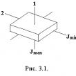
The law of the dynamics of rotational motion for the solid has the form: A similar expression can be obtained if we consider the rotational movement of the mechanical system relative to the fixed axis. In this case, the total moment of the momentum of the system is the total moment of the external forces attached to the system. If the total moment of all external forces acting on the physical object (system) is zero, i.e. The system is closed, then for a closed system. Hence: . The last expression is impulse moment: the moment of the closed system pulse is preserved (not changing) over time. This is the fundamental law of nature. It is associated with the character of symmetry of space - its isotropy. With the invariance of physical laws on choosing the direction of the coordinate axes of the reference system (relative to the rotation of the closed system in space per any angle). In order to maintain the position of the axis of rotation of the solid, over time, the bearings in which the axis holds is used. However, there are such axes of rotation of bodies that do not change their orientation in space without external forces on it. These axes are called free axes(or axes of free rotation). It can be proved that in any body there are three mutually perpendicular axes passing through the center of mass body, which can serve as free axes (they are called the main axes of inertiabody). For example, the main axes of the inertia of a homogeneous rectangular parallelepiped pass through the centers of opposing faces (Fig. 3.1). The main axes of the inertia of the ball are any three mutually perpendicular axes passing through the center of mass.
It can be shown that the rotation around the main axes with the greatest and smallest moments of inertia is sustainable, and rotation near the axis with the average moment - unstable. So, if you throw a body having a form of parallelepiped, bringing it simultaneously into rotation, then it falls, will steadily rotate around the axes 1 and 2 (Fig.3.1). The property of free axes to maintain its position in space is widely used in the technique. Most interesting in this regard gyroscopes- massive homogeneous bodies rotating with a large angular speed near their axis of symmetry, which is a free axis.
If the axis of the gyroscope is fixed with bearings, then as a result of the gyroscopic effect, gyroscopic forces acting on supports occur. Gyroscopes are used in various gyroscopic navigation devices (gyrocompass, girodorizont, etc.). Another important use of gyroscopes is to maintain a given orientation of an object in space (gyroscopic platforms). Lecture 11. Gyroscopes.This lecture discusses the following issues: 1. Gyroscopes. Free gyroscope. 2. Precession of the gyroscope under the action of external forces. Corner speed of precession. Nuting. 3. Gyroscopic forces, their nature and manifestation. 4. Wipes. The stability of the rotation of the symmetric top. The study of these issues is necessary in the discipline "Details of machines".
Gyroscopes.Free gyroscope.A gyroscope is a massive axially symmetric body, rotating with a large angular speed around its axis of symmetry. In this case, the moments of all external forces, including the force of gravity, relative to the center of mass gyroscope are zero. This can be implemented, for example, by placing a gyroscope in Cardanov suspension shown in Fig. 1. Fig.1 Wherein
and the moment of the impulse is preserved: L \u003d. const.(2) The gyroscope behaves the same way as the free of rotation body. Depending on the initial conditions, two variants of the gyroscope behavior are possible: 1. If the gyroscope is promoted around the axis of symmetry, then the direction of the moment of the pulse and angular velocity coincide: , (3) and the direction of the axis of the symmetry of the gyroscope remains unchanged. This can be verified by turning the stand on which the Kardanov suspension is located - with arbitrary corners of the support axis of the gyroscope retains the constant direction in space. For the same reason, the top, "running" on a sheet of cardboard and descended up (Fig. 2), retains the direction of its axis during the flight, and falling the edge to the cardboard, continues to rotate steadily until the stock of its kinetic energy is being resumed.
Fig.2 A free gyroscope, promoted around the axis of symmetry, has very significant stability. From the main equation of moments it follows that changing the moment of momentum
If time intervalsmall, then little, that is, with short-term impacts, even very large forces, the movement of the gyroscope varies slightly. The gyroscope seems to resist the attempts to change its moment of momentum and seems to be "hardened." Take a gyroscope cone-shaped form based on the rod of the stand in its center of mass o (Fig. 3). If the body of the gyroscope does not rotate, it is in a state of indifferent equilibrium, and the slightest push shifts it from the spot. If this body will lead to rapid rotation around its axis, even strong blows with a wooden hammer will not be able to significantly change the direction of the axis of the gyroscope in space. The stability of the free gyroscope is used in various technical devices, for example, in autopilot.
Fig. 3. 2. If the free gyro is promoted so that the vector instantaneous angular velocity and the axis of the gyroscope symmetry does not coincide (as a rule, this mismatch is insignificant), then the movement described as "free regular precession" is observed. In relation to the gyroscope it is called a nutation. With this axis of symmetry of gyroscope, vectorsL I. lie in the same plane that rotates around the directionL \u003d. const.with an angular speed equalwhere - The moment of inertia of the gyroscope relative to the main central axis perpendicular to the axis of symmetry. This angular velocity (calling it the speed of the nation) with the rapid proper rotation of the gyroscope turns out to be quite large, and the nation is perceived by the eye as a fine shake of the axis of the gyroscope symmetry. The nutal motion is easy to demonstrate using a gyroscope shown in Fig. 3 - It occurs when hitting the hammer along the rod rolling around its axis of the gyroscope. At the same time, the more stronger is the gyroscope, the more his moment of the impulseL. - the greater the speed of the nation and the "smaller" of the shake of the shape of the figure. This experience demonstrates another characteristic feature of the nation - over time, it gradually decreases and disappears. This is a consequence of inevitable friction in the hypocop support. Our land is a kind of gyroscope, and it is also typical of a typing movement. This is due to the fact that the earth is somewhat shoved from the poles, due to the moments of inertia relative to the symmetry axisand relative to the axis lying in the equatorial planediffer. Wherein, but . In the reference system associated with the Earth, the axis of rotation moves along the surface of the cone around the axis of the earth symmetry with an angular velocity W 0, that is, it makes one turn around for about 300 days. In fact, by virtue, as expected, the unabolute stiffness of the Earth is, this time is more - it is about 440 days. At the same time, the distance of the ground surface, through which the axis of rotation passes, from the point through which the symmetry axis (the North Pole) passes, is equal to just a few meters. The labeled movement of the Earth does not fade - apparently, the seasonal changes occurring on the surface Precession of the gyroscope under the action of external forces. Elementary theory.We now consider the situation when the force is applied to the axis of the gyroscope, the line of action of which does not pass through the consolidation point. Experiments show that in this case the gyroscope behaves quite unusual. If the axis is articulated at the point about the gyroscope (Fig. 4) to attach the spring and pull up with the forceF. , The axis of the gyroscope will be moved not in the direction of force, but perpendicular to it, Block. This movement is called a gyroscope precession under the action of external force.
Fig.4 Experienced way can be established that the corner speed of the precession depends not only on the amount of forceF. (Fig. 4), but also from what point of the axis of the gyroscope this force is attached: with increasingF and her shoulder l. Regarding the point of consolidation of the rate of precession increases. At the same time it turns out that the stronger the gyroscope is promoted, the less the corner speed of the precession in dataF I. l.. As force f causing a precession can act the strength of gravity if the constraint point of the gyroscope does not coincide with the center of the masses. So, if the rod with a fast rotating disk is suspended on a thread (Fig. 5), then it does not go down, as it could be assumed, but makes a precession movement around the thread. The observation of the precession of the gyroscope under the action of gravity in a sense is even more convenient - the line of action "automatically" shifts together with the axis of the gyroscope, while maintaining its orientation in space.
Fig.5 Other examples of precession can also be given - for example, the movement of the axis of a well-known children's toys - Yula with a pointed end (Fig. 6). Yula, promoted around his axis and put on the horizontal plane slightly obliquely, begins to precess around the vertical axis under the action of gravity (Fig. 6).
Fig.6. The exact solution of the problem of movement of the gyroscope in the field of external forces is quite an expression for the angular velocity of the precession can be easily obtained within the framework of the so-called elementary gyroscope theory. In this theory, the assumption is made that the instantaneous angular speed of rotation of the gyroscope and its moment of impulse is directed along the axis of the symmetry of the gyroscope. In other words, it is assumed that the angular speed of rotation of the gyroscope around its axis is significantly larger than the corner speed of the precession: so contribution toL. due to the precession movement of the gyroscope, you can neglected. In this approximation, the moment of the gyroscope impulse is obviously equal to where - Moment of inertia relative to the symmetry axis. So, consider a severe symmetric gyroscope, in which a fixed point S (Point of support about the stand) does not coincide with the center of mass O (Fig. 7).
Fig.7. Moment of gravity relative to the point s where θ - The angle between the vertical and axis of the symmetry of the gyroscope. The vector M is aimed at normal to the plane in which the axis of the symmetry of the gyroscope and the vertical spent through the point S (Fig. 7). The support force of the support passes through S, and its moment relative to this point is zero. Changing the moment of impulseL. Determined by the expression dL= MDT.(8) At the same time I. L, and the top axis is precedes around the vertical direction with angular speed. Once again we emphasize: the assumption is made that condition (5) is performed and that L is constantly directed along the axis of the symmetry of the gyroscope. Figure 95 it follows that In vector (10) Comparing (8) and (10), we obtain the following relationship between the moment M, the moment of the pulse L and the angular speed of the precession: (11) This ratio allows you to determine the direction of the precession at a given direction of rotation of the wolf around its axis. We note that M determines the angular velocity of the precession, and not an angular acceleration, so the instantaneous "shutdown" M leads to the instantaneous disappearance of the precession, that is, the precession movement is non-indication. The force causing a precession movement can have any nature. To maintain this movement, it is important that the moment of the Moment M turns along with the axis of the gyroscope. As already noted, in case of gravity, this is achieved automatically. At the same time from (11) (see also Fig. 7) You can get: (12) If we consider that in our approximation, the relation (6) is true, then for the corner speed of the precession we get
It should be noted thatdepends on the cornertilt axis gyroscope and back proportional w, which is well consistent with experienced data. Precession gyro floor by the action of external forces. Departure from the elementary theory. Nuting.Experience shows that the precession movement of the gyroscope under the action of external forces is generally more complicated than what was described above in the framework of the elementary theory. If you inform the gyroscope push, changing the angle(see Fig. 7), then the precession will cease to be uniform (often say: regular), and will be accompanied by small rotations and trembling the tops of the gyroscope - nation. To describe them, it is necessary to take into account the inclusion of the full moment of the pulse L.Instant angular speed of rotationw. and the axis of symmetry of the gyroscope. The accurate theory of the gyroscope goes beyond the framework of the course of general physics. From the relationshipdL= MDT.it follows that the end of the vector L. Moves in the direction M., that is, perpendicular to the vertical and to the axis of the gyroscope. This means that vector projections L. on verticalL B. And on the axis of the gyroscopeL 0. remain constant. One more constant is energy (14) where T. - kinetic gyroscope energy. ExpressingL B, L 0 and T Through the angles of Euler and their derivatives, it is possible, using the Euler equations, describe the movement of the body analytically. The result of such a description is as follows: moment of momentum of pulse L. Describes the precession cone fixed in the space, and at the same time the axis of symmetry of the gyroscope moves around the vector L. on the surface of the cone of the nutation. The vertex of the module cone, like the top of the precession cone, is at the point of pinning a gyroscope, and the axis of the nouting cone coincides towards L.and moves with him. The angular velocity of the nutation is determined by the expression
where I. - moments of the inertia of the body of the gyroscope relative to the symmetry axis and relative to the axis passing through the support point and perpendicular axis of symmetry,- angular speed of rotation around the axis of symmetry. Thus, the axis of the gyroscope participates in two movements: nouting and precession. The trajectories of the absolute movement of the vertex of the gyroscope are intricate lines, the examples of which are presented in Fig. eight.
Fig.8. The nature of the trajectory along which the top of the gyroscope is moving, depends on the initial conditions. In the case of fig. eight, but The gyroscope was reclosed around the axis of symmetry, installed on a stand at a certain angle to the vertical and carefully released. In the case of fig. eight, b.he, in addition, was reported to some push forward, and in the case of fig. eight, in - push back along the precession. Curves in fig. 8 is quite similar to the cycloids described by the point on the wheel rim, riding a plane without slippage or slipping into one direction or another. And only by informing the gyroscope, the initial push of a completely certain amount and direction can be achieved that the axis of the gyroscope will be preceded without nutation. The faster the gyroscope rotates, the greater the angular velocity of the nutation and the less their amplitude. With a very rapid rotation of the nation are made practically imperceptible to the eye. It may seem strange: why the gyroscope, being promoted, is set at an angle to the vertical and released, does not fall under the action of gravity, but moves a sideways? Where does the kinetic energy of precession movement be taken? Answers to these questions can be obtained only within the framework of the exact theory of gyroscopes. In fact, the gyroscope really begins to fall, and the precession movement appears as a consequence of the law of preservation of the moment of impulse. In fact, the deviation of the axis of the gyroscope down leads to a decrease in the projection of the moment of the pulse to the vertical direction. This decrease should be compensated by the moment of the pulse associated with the precession movement of the axis of the gyroscope. From an energy point of view, the kinetic energy of the precession appears due to changes in the potential energy gyroscopes. If, due to the friction in the title support, the gyroscope is faster than the rotation of the gyroscope around the axis of the symmetry (as a rule, it happens), shortly after the "launch" of the gyroscope of the gyro disappear and the net precession remains (Fig. 9). In this case, the angle of inclination of the axis of the gyroscope to the verticalit turns out more than he was at the beginningthat is, the potential energy of the gyroscope decreases. Thus, the axis of the gyroscope should fall a little to be able to precess around the vertical axis.
Fig.9. Gyroscopic forces.Let us turn to the simple experience: Take the tree AU with a wheel planned on him FROM (Fig. 10). While the wheel is not promoted, it does not represent any work turning the shaft in space arbitrarily. But if the wheel is promoted, then attempts to rotate the shaft, for example, in a horizontal plane with a small angular speedlead to an interesting effect: the tree seeks to escape from the hands and turn in the vertical plane; It acts on hands with definite forcesR a and R b (Fig. 10). It is required to apply a tangible physical force to keep the shaft with a rotating wheel in a horizontal plane.
Fig. 10 Consider the effects arising from the forced rotation of the axis of the gyroscope in more detail. Let the axis of the gyroscope be strengthened in the U-shaped frame, which can rotate around the vertical axis OO "(Fig. 11). Such a gyroscope is usually called non-free - its axis lies in the horizontal plane and cannot be exit.
Fig. eleven We will spout a gyroscope around it around its axis of symmetry to a large angular velocity (moment of pulse L) and turn the frame with a gyroscope that is reinforced in it around the vertical axis OO with some angular speed.as shown in Fig. 11. The moment of impulse L, will receive incrementdL which should be provided with the moment M forces attached to the axis of the gyroscope. Moment M, in turn, created a pair of forcesarising from the forced rotation of the axis of the gyroscope and acting on the axis from the side of the frame. According to the third law of Newton, the axis acts on the frame with the forces(Fig. 11). These forces are called gyroscopic; they create a gyroscopic moment. The appearance of gyroscopic forces is called a gyroscopic effect. It is these gyroscopic forces that we feel trying to turn the axis of the rotating wheels (Fig. 10). The gyroscopic moment is easy to calculate. Put according to the elementary theory that (16) where j. - the moment of inertia of the gyroscope relative to its axis of symmetry, andω - angular speed of own rotation. Then the moment of external forces acting on the axis will be equal to (17) where Ω. - Corner speed of forced rotation (sometimes they say: forced precession). From the side of the axis on the bearings acts the opposite moment (18) Thus, the shaft of the gyroscope shown in Fig. 11, will be pressed up in the bearing in and put pressure on the lower part of the Bearing A. The direction of gyroscopic forces can be easily found using the rule formulated by N.E. Zhukovsky: Gyroscopic forces tend to combine the moment of the pulse L of a gyroscope with the direction of the angular velocity of forced rotation. This rule can be visually demonstrated using the device shown in Fig. 12.
Fig. 12 The axis of the gyroscope is fixed in the ring, which can be freely rotated in the clip. We give the clip to rotation around the vertical axis with an angular speed(forced rotation), and the ring with a gyroscope will be rotated in the clip until the directions l anddo not coincide. Such an effect underlies the well-known magnetic phenomenon - the magnetization of the iron rod during its rotation around its own axis - at the same time, the spins of the electrons are built along the axis of the rod (Barnett experience). Gyroscopic efforts are experiencing bearings of the axes of fast rotating parts of the machine when turning the machine itself (turbine on the ship, the screw on the plane, etc.). With significant values \u200b\u200bof the angular velocity of forced precessionand own rotationas well as large sizes of the flywheel, these forces may even destroy bearings. Consider some examples of manifestation of gyroscopic forces. Example 1. A light single-engine aircraft with the right screw makes the left turn (Fig. 13). The gyroscopic moment is transmitted through the bearings A and B on the aircraft body and acts on it, trying to combine the axis of the proper rotation of the screw (vector) with the axis of forced precession (vector). The plane begins to lay down the nose up, and the pilot must "give a handle from itself," that is, to lower down the height steering wheel. Thus, the moment of gyroscopic forces will be compensated by the moment of aerodynamic forces.
Fig. 13 Example 2.With a ships killeep (from the nose on the feed and back), the speed turbine rotor participates in two movements: in rotation around its axis with angular speedand in turn around the horizontal axis perpendicular to the turbine shaft, with angular speed(Fig. 14). At the same time, the turbine shaft will put pressure on bearings with forceslying in a horizontal plane. When rolling, these forces, like a gyroscopic moment, periodically change their direction to the opposite and can cause the "lying" of the ship, if it is not too large (for example, a tug).
Fig. fourteen Suppose the mass of the turbinem.\u003d 3000 kg its inertia radiusR. IN.\u003d 0.5 m, turbine rotation speedn.\u003d 3000 rpm, maximum corner speed of the vessel case with killery\u003d 5 hail / s, distance between bearingsl.\u003d 2 m. The maximum value of the gyroscopic force acting on each of the bearings is After substitution of numeric data, we getthat is about 1 ton. Example 3. Gyroscopic forces can cause the so-called oscillations of the "Shimmi" wheels of the car (Fig. 15) [V.A. Pavlov, 1985]. Wheel rotating around AA axis with angular speedw. At the time of the obstacle, an additional rate of forced rotation around the axis perpendicular to the pattern is reported. In this case, the moment of gyroscopic forces occurs, and the wheel will start turning around the BB axis. "When purchasing angular rotation speed around the BB axis," the wheel will start turning around the axis, perpendicular to the pattern, deforming the elastic suspension elements and causing strength to return the wheel to the previous vertical position. Next, the situation is repeated. If in the design of the car, do not adopt special measures that have arisen "Shimmi" fluctuations can lead to a breakdown of tires from the wheel rim and to break the parts of its attachment.
Fig. fifteen Example 4. With a gyroscopic effect, we are confronted while driving on a bike (Fig. 16). Making, for example, turn right, the cyclist instinctively shifts the center of gravity of his body to the right, as if a bike bike. Arriving bike forced rotation with angular speedleads to the appearance of gyroscopic forces with the moment. In the rear wheel, this moment will be repaid in bearings, rigidly related to the frame. The front wheel with respect to the frame is the freedom of rotation in the steering column, under the action of a gyroscopic moment, will begin to rotate precisely in the direction that it is necessary for the right turn of the bicycle. Experienced cyclists make such turns, which is called, "without hands."
Fig. sixteen The question of the occurrence of gyroscopic forces can be considered from another point of view. It can be assumed that the gyroscope shown in Fig. 11, participates in two simultaneous movements: relative rotation around its own axis with an angular velocity W and a portable, forced rotation around the vertical axis with an angular speed. Thus, elementary masseswhich can be divided by the gyroscope disk (small mugs in Fig. 17) must experience Coriolis acceleration (20) These accelerations will be maximal for masses currently in time on the vertical diameter of the disc, and are zero for masses, which are on the horizontal diameter (Fig. 17).
Fig. 17. In the reference system rotating with the angular speed(In this reference system, the axis of the gyroscope is fixed), on the massescoriolis forces inertia will act (21) These forces create a momentwhich seeks to turn the axis of the gyroscope so that the vectorcombined with. Moment must be balanced by the moment of reaction forcesacting on the axis of the gyroscope from the bearing. According to the third law of Newton, the axis will act on bearings, and through them and on the frame, in which this axis is fixed with gyroscopic forces. Therefore, it is said that gyroscopic forces are due to the forces of Coriolis. The occurrence of coriolis forces can be easily demonstrated if instead of a hard disk (Fig. 17) take a flexible rubber petal (Fig. 18). When you turn the shaft with the promoted petal around the vertical axis of the petal bends when the vertical position is passed as shown in Fig. eighteen.
Fig. eighteen Wipes.The wipes differ fundamentally from gyros by the fact that in the general case they do not have a single fixed point. Arbitrary wolf movement has a very complex character: being curved around the axis of symmetry and put on the plane, they precessively "run" along the plane, prescribing intricate figures, and sometimes even turn away from one end to another. Without going into the details of such an unusual behavior of the wolf, we only note that the friction force arising at the point of contact with the wolf and the plane occurs an important role here. Let us briefly focus on the question of the stability of the rotation of the symmetric top of an arbitrary shape. Experience shows that if the symmetrical top of the symmetry is rotated around the axis of symmetry and set to the plane in a vertical position, then this rotation, depending on the shape of the top and the angular rotational speed, will be either stable or unstable. Let there be a symmetrical top shown in Fig. 19. We introduce the following notation: O - Mass Cass,h.- the distance from the center of the masses to the point of the support; K - the center of the curvature of the wolf at the point of the support,r.- radius of curvature;- moment of inertia relative to the symmetry axis,- moment of inertia with respect to the main central axis perpendicular to the axis of symmetry. And fig. 21. It should be noted that in the process of turning the flap, the resulting momentum of the pulse retains its original direction, that is, vector L, all the time is directed vertically upwards. This means that in the situation shown in Fig. 21, b.When the top axis is horizontal, there is no rotation around the axis of the symmetry of the Wolf! Next, when tipping over the leg, rotation around the axis of the symmetry will be opposite to the source (if you look at all the time from the leg side, Fig. 21, in). In the case of an egg-shaped top, the body surface in the neighborhood of the support point is not a sphere, but there are two mutually perpendicular directions for which the radius of curvature at the support point takes extreme (minimum and maximum) values. Experiments show that in the case shown in Fig. 21, butThe rotation will be unstable, and the top takes a vertical position, spinning around the axis of symmetry and continuing the steady rotation at a sharper end. This rotation will continue until the friction force is gone sufficiently the kinetic energy of the wolf, the angular speed will decrease (will become lessω 0 ), and the top will fall.
Fig. 22. Questions for self-test What solid is called a gyroscope? What is equal and how is the kinetic moment of a fast-growing gyroscope relative to its fixed point? What physical properties have a quick-growing gyroscope with three degrees of freedom? What effect makes the action of the same force applied to the axis of the fixed and fast-growing gyroscope with three degrees of freedom? Output the formula to calculate the corner speed of the precession axis of the gyroscope. What is the difference in the properties of gyroscopes with two and three degrees of freedom? What is the physical essence of the gyroscopic effect and under what conditions is it observed? What formulas are the dynamic reactions of bearings, in which the frame rotates a rotating gyroscope with two degrees of freedom? Literature 1. A.N. Matveyev. Mechanics and theory of relativity. M.: Higher School, 1986. 2. S.P. Shooters. Mechanics. M.: Science, 1975. 3. S.E. Haikin. Physical bases of mechanics. M.: Science, 1971. 4. D.V. Sivukhin. General physics course. T.1. Mechanics. M.: Science, 1989. 5. R.V. Paul. Mechanics, acoustics and teachings about warmth. M.: Science, 1971. 6. R. Feynman and others. Fainman lectures in physics. M.: Mir, 1977. applied mechanics Machine parts Theory of machines and mechanisms A gyroscope is called massive te-lo, quickly rotating around one of its main axes of inert. The change in the moment of the amount of the amount of gyro movement as a result of the action on it is called external forces called preceive. The accurate calculation of the speed of the precession is complex. In the first, the commemoration is taken that the axis of rotation of the gyroscope, the instantaneous axis of rotation and the direction of the moment of the number of movement coincide. Therefore, the precession can be observed if you follow the movement of the axis of the gyroscope. There are gyroscopes with three degrees of freedom(the axis of possible rotation) of the gyroscope rotor is provided by two frames of the suspension cardanov. If there is no external perturbation to such a device, the axis of its own rotation of the rotor retains a constant direction in space. If the moment of external force acts on it, seeking to turn the axis of its own rotation, then it begins to rotate not around the direction of the moment, but around the axis perpendicular to it (precession). Fig. 1. Gyroscope with three degrees of freedom (With two frames of Cardanova suspension), kinematic scheme. I. y is the axis of its own rotation of the rotor, along which his kinetic moment is directed; I. 0 - reference direction of the kinetic moment; j. - angle of deviations of the inner frame of Cardanova suspension; w. j - angular rotation speed of the inner frame of the suspension (precession); M. q is the moment of indignant external force; w. Q - angular rotation speed of the external frame of the suspension (nation). In a well-balanced (ashistatic) and fairly rapidly rotating gyroscope, installed on highly superb bearings with minor friction, the moment of external forces is practically absent, so the gyroscope has long retains almost unchanged its orientation in space. Therefore, it may indicate an angle of rotation of the base on which it is fixed. It is so French physicist J. Fux (1819-1868) for the first time visually demonstrated the rotation of the Earth. If the turn of the axis of the gyroscope is limited to the spring, then with the corresponding installation of it, say, on the aircraft that performs a reversal, the gyroscope will deform the spring until the moment of external force is equalized. In this case, the compression force or stretching the spring is proportional to the angular velocity of the aircraft. This is the principle of action of an aviation indicator of rotation and many other gyroscopic devices. Since friction in the bearings is very small, a lot of energy is not required to maintain rotation of the rotor of the gyroscope. To bring it to rotation and to maintain rotation, there is usually a sufficiently low-power electric motor or a jet of compressed air. Figure 1 shows a hy-Roskop, fortified in the cardan suspension. Outdoor Ring BUT Cardanova suspension can turn freely around the vertical axis AA . Inner ring B. Communication with ring BUT horizontal axis bB. In the ring B.gyroscope has strengthened G axis of the nec eV Perpendi-Qular BB axis. The center of gravity of the gyroscope is on the re-section of all three axes and at any turn of the rings kept its position in simple. The movement of the gyroscope with the Zak-repinted center of gravity is described by the Moent Equation where M - moment of external forces N - The moment of the amount of gyroscope movement. Further calculations are explained by vector circuit. 2; The location of the gyroscope and the designations of the axes are the same as in Fig. one.  Let it be at first M. \u003d 0, and the gyroscope rotates with the corner, speed, so that n \u003d j (J. The moment of inertia of the gyroscope relative to the axis of rotation). If then to the axis of the gyroscope, live vertical external force R, then the moment will arise M, lying in a horizontal plane. Replying to equation (1) and fig. 2 and 3, it is not difficult to understand that vectors M. and N. Oltroy-Nalna each other, and vector dN. directed just like M, therefore, power R, Without changing the magnitudes of the vector / V, makes it the end to describe the circle in the horizontal plane. Per  fig.2 time dt. Projection of vector N. The horizontal plane will return to the angle D, and, as follows from (1) and fig. 2, where a is an angle that vector N. makes up with a vertical. Thus, the angular speed Q of the rotation of the vector N. equal or in vector form [ N] \u003d m (2`) If the axis of the horizontal gyroscope (Fig. 3), then instead. (2) we get In a rapidly rotating gyroscope, the direction of the moment of the amount of movement approximately coincides with the direction of the axis of the gyroscope itself. Therefore, under the action of an external moment M. The axis of the gyroscope will also turn around the vertical axis with angular speed , Describing in the cone space. Since vector M. Turns together with n in such a way that their mutual location does not change over time, the rotation of the axis of the gyroscope with constant strength R It turns out to be uniform. This rotation is called regular precession, and the value is an angular rate of precession. As noted above, the above-mentioned reference only for a rapidly rotating gyroscope, i.e., Let's say a few words about inequality (3). It is easy to see that the vector of the total moment of the amount of movement of the gyroscope in the presence of a precession contains two components: J) and J1 (J1 -the moment of the inertia of the gyroscope relative to its diameter). Thus, the full moment of the amount of movement N, Strictly speaking, does not coincide in the direction of the angular velocity vector (with the axis of the gyroscope). These non-fall, it is possible, however, prene-shave with J1 J. Moments of Inertia J. and J1v our case turns out to be the values \u200b\u200bof one order; In this case, the condition of the applicability of formula (4) is inequality (3), which. In conventional gyroscopes, it is very good (values \u200b\u200band differ from each other at least three orders of magnitude). In this paper, it is necessary to determine the angular speed of the rotation of the gyroscope on its regular precession. Experimental installation and measurement technique. Gyro (Fig. 1) is a miniature electric motor 1, Overacted to a horizontal rod. The rod together with the gyroscope can rotate in the vertical plane around the axis, strengthened in the fork 2. The rotation in the horizontal plane occurs along with the fork in the suspension 3. To increase the moment of inertia, the engine is equipped with a flywheel 4. The motor is powered by a constant current.  Fig.1 An equalized gyroscope and turn on the motor. Even with all possible care in balancing, the gyroscope begins to slowly precess, turning in the horizontal plane. This happens, obviously, because the vertical axis of rotation of the Gi-Roscope does not pass exactly through its center of mass. Consequently, the Ment of gravity, as well as the moment of friction force relative to the vertical axis is different from zero. Equation (2) For this case can be written in the form: where My - The moment of strength of the strength and friction belongs to the vertical axis. Replacing in equation (4) Corner speed peri-one, we get: Keeping the speed of the rotation of the gyroscope is unchanged (without changing the voltage filed by the motor); drink free end gyroscope rod by weight weight Pi hiding it at a distance, / i from the vertical axis of rotation. The moment of gravity will take a new meaning: but and therefore (7) Sublated (5) on (7), we get The last equality can serve to verify relation (2). The task. Make a measurement of the rate of precession of the equalized gyroscope at three positions (/ cargo different from the equilibrium position. For measurement, feed the voltage 220 V to the engine winding , and wait 2--3 min Holding the rod in the horizontal polo. Smoothly release the rod and calculate the time of three complete rims of the rod with the help of Cendomer. Having finished the measurement of the speed of the precession, submit to the winding of the motor Voltage 200 V. Give the motor to unwind, and then turn it off for time while the motor movement slows down, make 3--4 per measure of the precession period. Check the equality (8) according to measurement data. Control questions. one. What assumption is the basis of the approximate the theory of the gyroscope? 2. What part of the moment of inertia remained unaccounted when calculating the moment of inertia of the flywheel? How to rudely take into account her? 3. What qualitative conclusion can be made from the precession observation when the engine is turned off? 4. Explain the emergence of the precession of the children's checker. The use of gyroscopes. The gyroscope is the main part of the instruments such as a pointer course, turning, horizon, side of the light, gyrocompass. Inside these devices rotate at a rate of several tens of thousands of revolutions per minute small rackers, fortified in the cardanov suspension. The body of the device can be rotated as you like, while the axis of the rotating gyroscope will maintain a constant position in space. Greeting devices are used to automatically control the movement of aircraft and ships. To maintain a given course of the ship serves<авторулевой>and aircraft -<автопилот>. IN instrument<авторулевой> a free gyroscope with a large moment of pulse and a low friction force in the places of Cardanova suspension was applied. The direction of the ship moves is given by the direction of the axis of the free gyroscope. With any deviations of the ship from the course, the axis of the gyroscope retains its former spatial direction, and the Kardanov suspension turns relative to the vehicle body. Rotate the frame of the Cardanov suspension is monitored using special devices that give commands to machine guns on the steering wheel and return the ship to the specified course. <Автопилот> Equipped with two gyroscopes. One of them has an axis vertically and in such a position, a gyroscope is spinning. The vertically located axis of the gyroscope sets the horizontal plane. The axis of the second gyroscope is horizontally, orienting it along the axis of the aircraft. This gyroscope constantly "knows" the aircraft course. Both gyroscope give the appropriate commands to control mechanisms supporting the flight of the aircraft at the specified course. Currently, autopilot are equipped with all modern aircraft intended for long flights. The gyroscope serves as an important part in the system of control systems of spacecraft. Gyroscopes are used in the navigation systems. Inertial navigation
Refers to such a way of determining the location in space, in which these external sources are not used. All sensitive elements are directly on board the vehicle. Inertial linear acceleration meters - accelerometers
Installed on the so-called gyrostabilized platform
. This platform using the gyroscope properties is to maintain the unchanged orientation of its axis in space, provides a strictly horizontal position of the axleterometer sensitivity axes (with an accuracy of units of angular seconds). The measured accelerations are integrated twice, and thus information about the increment of the location of the movable object is obtained. United common task of determining the coordinates of the movable object, gyroscopes and accelerometers form inertial navigation system
(INS). In addition to this task, the INS delivers information about the angular orientation of the object: the corners of the roll, pitch and lying (course) and the speed of the object. The gyroscope is most often used as a sensitive element of indicating gyroscopic devices and as a rotation angle sensor or an angular velocity for automatic control devices. In some cases, for example, in gyrostabilizers, gyroscopes are used as generators of the moment of force or energy. The main areas of application of gyroscopes are shipping, aviation and cosmonautics. Consider inertial navigation detail -the method of measuring the acceleration of the vessel or the aircraft and determining its speed, position and distance passed from them from the source point using the autonomous system. Inertial navigation systems (guidance) produce navigation information and data for control overboard aircraft, rockets, spacecraft, ships and submarines. Theoretical basis.Acceleration There is a speed of speed changes, and speed - speed changes. Measuring the acceleration of the movement, it is possible by integrating it to calculate the speed. By integrating the speed, you can determine the current location (coordinates) of the aircraft or vessel. Thus, the system of inertial navigation is a path numbering system. Acceleration is a vector value that has not only a numerical value, but also direction. Consequently, the system of sensors determining the acceleration should measure its value and its direction. Accelerometer measures the magnitude. Information on the direction gives gyroscopes that provide the reference coordinate system for accelerometers. Accelerometers, measuring actual acceleration, say, aircraft, at the same time react to the gravitational field. To compensate for this acceleration, the inertial navigation system deducts the calculated value from the output of accelerometers g.. Value g. It is calculated as a function of the location (coordinate), in particular longitude and latitude. So, the inertial navigation system measures the apparent acceleration into which it includes acceleration of gravity. Then she, twice integrating this magnitude, finds a location. Finally, based on this calculated location, calculates the magnitude g,which is subtracted from the apparent acceleration. Such a second-order feedback system (Fig. 1) behaves like a very low frequency oscillation generator in two orthogonal horizontal directions. Period of oscillations at sea level is 84 min; They are called the oscillations of the Shulera named by the German inventor M. Shulera, patented in 1908 the first practically suitable gyrocompass.  Fig. 1. inertial navigation system With feedback. The system measures the apparent acceleration (which includes speeding acceleration g.) And, twice integrating it, finds the location, then with the latter, the acceleration determines g. And, sulfing from the apparent acceleration, finds the true acceleration of the movement of the aircraft or the vessel. System options.In previous inertial navigation systems, the reference coordinate system was provided by installing accelerometers and gyroscopes on a stabilized platform in a cardan suspension. Such a suspension was isolated by the platform from the turns of the aircraft or the vessel. This made it possible to hold accelerometers in constant orientation relative to the Earth when the object moves. In modern inertial navigation systems, computers are applied following the orientation of accelerometers. Such systems are called free. The output of gyroscopes come directly to the computer, which calculates the instantaneous direction of accelerometers in the coordinate reference system and the corresponding corrective signals. Inertial devices.The main devices of the inertial navigation system are accelerometers and gyroscopes. The accelerometer of the most common type is a sensitive mass associated with the body of a spring of this or that kind. The spring can be mechanical, but most often it is an electric (electromagnetic, electrostatic or piezoelectric) device that creates opposing power. When the housing is deviated (relative to the mass) caused by the applied acceleration, a signal appears. Electronic amplifier, amplifying this signal, creates an appropriate acceleration of the spring force (applied to mass), which in the feedback system reduces the mismatch signal to zero (Fig. 2).  Fig. 2. Accelerometer. The acceleration of the motion causes a deviation of the sensitive mass, fixed on the elastic hinge. The deviation sensor signal is amplified and creates a proportional acceleration of the spring-appropriate force applied to the sensitive mass, thereby returning the sensor signal to zero value.  In the guidance systems of ballistic missiles and cosmic aircraft, where the accuracy of determining the speed is critical, a gyroscope reaction was previously used as opposing power, and the acceleration was automatically integrated to find speed. In a conventional mechanical gyroscope by means of a rotating rotor similar to Julia, a fixed direction is maintained in space. In order for the device is stable enough for inertial navigation purposes, friction and other disturbing effects should be excluded. Therefore, accurate importance are of great importance. Fig. 2. Course Aviation Gaukel with air drive. An example of the use of a three-particle gyroscope. Arrethir is used to hold the axis of its own rotation of the rotor in a horizontal position when entering azimuth on the scale. 1 - base; 2 - gear wheel of the synchronizer; 3 - Arretar handle; 4 - arrethir; 5 - azimuth scale; 6 - air nozzle; 7 - outer frame; 8 - rotor; 9 - body; 10 - semi-axle of the outer frame with the fixative nut; 11 - Inner frame. calculations and care of gyroscopic instruments. However, the main reason for the error in the mechanical gyroscope is friction in moving parts. An example of the use of a three-bearing gyroscope in an aviation rate of the course (Gyropolucompace). Rotation of the rotor in ball bearings is created and supported by a stream of compressed air directed to the corrugated rim surface. Internal and outer frames of the Cardanova suspension provide complete freedom of rotation of the axis 1. Free axis of rotation. Consider two cases of rotation of a solid rod relative to the axis passing through the center of mass. If you promote the rod relative to the axis Oo. And to give it to yourself, that is, to free the axis of rotation from the bearings, then in the case of Fig.71 - and the orientation of the free rotation axis relative to the rod will change, since the rod under the action of a pair of centrifugal inertia forces will turn into a horizontal plane. In the case of Fig.71, the moment of the pair of centrifugal forces is zero, so the promoted rod will continue to rotate around the axis Oo And after her release. The axis of rotation, the position of which in space is saved without the action of any forces from the outside, is called the free axis of the rotating body. Consequently, the axis perpendicular to the rod and passing through its mass center, there is a free axis of the rod rotation. Any solid body has three mutually perpendicular free axis of rotation, intersecting in the center of the masses. The position of the free axes for homogeneous bodies coincides with the position of their geometric axes of symmetry (Fig.72).
Parallelepiped has all three axes fixed. The cylinder is fixed only one axis coinciding with a geometric axis. Share all three axes are not fixed. Free axis of rotation are also called the main axes of inertia. With free rotation of the bodies around the main axes of inertia, only rotation around those axes, which correspond to the maximum and minimum meaning of the moment of inertia are stable. If there are external forces on the body, it turns out to be stable only around the main axis, which corresponds to the maximum moment of inertia. 2. Gyroscope(from Greek gyreuo. - Rotating I. skopeo. - I see) - the homogeneous body of rotation quickly rotating around the axis of the symmetry, the axis of which can change the position in space. When studying the movement of the gyroscope, we believe that: but. The center of mass gyroscope coincides with its fixed point O.. Such a gyroscope is called balanced.
Q. Gyroscope pulse moment vector L. coincides with the angular velocity vector w. Since the gyroscope rotates around the main axis of the inertia. Let the axis of the gyroscope operate F. during the time D t.. According to the second law of the dynamics for rotational motion, so that a change in the moment of the pulse of the gyroscope during this time, (26.1) where r. - radius vector spent from a fixed point O. to the point of action (Fig.73). Changing the moment of the pulse of the gyroscope can be viewed as a turn of the axis of the gyroscope at an angle with an angular speed Here - normal to the axis of the gyroscope component of the strength acting on it. Under the action of power F. applied to the axis of the gyroscope, the axis turns not in the direction of force, but in the direction of the force M. relatively fixed point O.. At any time, the rotation rate of the axis of the gyroscope is proportional to the moment the moment of force, and with the constant shoulder of force - is proportional to the power itself. In this way, the movement of the axis of the gyroscope is irregular. This is the only case of unifying movement in the mechanics. The movement of the axis of the gyroscope under the action of external force is called forced precessia Gyro (from Latin Praecessio - movement ahead).
dQ \u003d.W. dt \u003d.(rF / IW.)dt.. (26.3) If the point of the application of force does not change, then r.\u003d Const and when integrating we get. q \u003d.(26.4) The integral in each case depends on the type of function ( t.). Under normal conditions, the angular speed of rotation of the gyroscope is very large, so the numerator is most often a lot less denominator, and there is an angle q. - Small value. The rapidly rotating gyroscope is resistant to the blow - the greater the greater the moment of the impulse. 4. Interestingly, force, under the action of which the axis of the gyroscope precessives, does not work. This is because the gyroscope point to which the force is applied, at any moment shifts in the direction perpendicular to the direction of force. Therefore, the scalar product of force on the small movement vector is always zero. Forces in such a manifestation are called gyroscopic. So, always gyroscopic is the Lorentz power acting on an electrically charged particle by the magnetic field in which it moves.
Distinguish 4 types of equilibrium: sustainable, unstable, saddle and indifferent. but. The position of the TT equilibrium is stable if with small deviations from equilibrium on the body the forces are beginning to act, seeking to return it to the equilibrium position. Figure 75 shows the situations of stable equilibrium bodies in the field of gravity. Gravity forces are massive forces, therefore, the resultant forces of gravity acting on the point elements TT is applied to the center of mass. In such situations, the center of the masses are called the center of gravity. A stable position of equilibrium corresponds to a minimum of potential body energy.
in. Seddling is such an equilibrium when, when moving by one degree of freedom, the balance of the body is stable, and when moving along another degree of freedom - unstable. In the situation shown in Figure 77, the position of the body relative to the coordinate x. is stable, and in relation to the coordinate y. - unstable. g. If, with the deviation of the body, there are no forces in the position of the equilibrium, seeking to shift the body in one direction or another direction, the position of the equilibrium is indifferent. For example, a ball in the field of gravity in an equipotential surface, a solid, suspended at the center of the center of the masses (at the point of the center of gravity) (Fig. 78).
In cases where the body relies on the support, the larger the area of \u200b\u200bthe support and the lower the center of gravity, the more stable the balance of the body (Fig.79). The main errors of gyroscopes are own care, cardannaya error, virable error and apparent care.
The accuracy of the coincidence of the center of gravity of the gyroscopic system with the suspension point (balance), the magnitude of the friction force in the axes of the cardan suspension, the weight, diameter and the speed of rotation are the determining stability factors of the axis of the gyroscope. When exposed to the cardan system of external forces, the axis of the gyroscope moves in the plane perpendicular to the direction of force. Such a movement of the gyroscope is called precessia. Precession It stops with the termination of the impact on the gyroscope. In aircoruses, it is required to hold a gyroscope in a vertical position in evolution and changing the speed of La. To reduce accumulating errors, it is necessary to adjust the position of the gyroscope with the mechanisms vertical correction. The vertical sensor uses the pendulum correction systems that follow the lower end of the gyroscope axis are directed towards the center of the Earth. Pendulum systems are affected by accelerations arising from maneuvering. As an example, it is possible to bring a phenomenon called the "airborne chamber" (indication other than zero, values \u200b\u200bof pitch or roll in rectilinear flight after the maneuver is completed). Therefore, at the maneuvering stages, the correction system is turned off. The accuracy of the testimony of the gyroscope will depend on the correction rate, the speed of one's own care, the parameters of the correction switch. In the first pneumatic air regions, the correction was not disconnected on the prience. Therefore, the correction speed was chosen very small so that the care of the gyroscope was not significant during the varyrage. Accordingly, the recovery time of the vertical increase. Later, the correction began to turn off in the rotation, and on some, and at accelerations (AGD -1). Currently, inertial hyftications are used, in which the accuracy is achieved by creating an artificial pendulum "long", equal to the radius of the Earth. Compacted by seeming care Gyro is a pointer |
 For the stability of rotation, it is of great importance, which one of the free axes serves as the axis of rotation of the body.
 In order for the axis of the gyroscope changed its direction in space, it is necessary to difference from zero of the moment of external forces. If the moment of the external forces applied to the rotating gyroscope, relative to its center of mass differ from zero, then there is a phenomenon that received the name of the gyroscopic effect. It consists in the fact that under the action of a pair of forces applied to the axis of the rotating gyro (Fig. 3.2), the axis is deviated in the direction perpendicular to the direction of force. The gyroscopic effect is explained by the fact that the moment of forces is directed along the direct about 2 o 2. During the DT, the moment of the gyro pulse will gain increment, coated with the moment vector. The direction of the vector coincides with the new direction of the axis of rotation of the gyroscope. Thus, the axis of rotation of the gyroscope turns around the straight line about 3 o 3. The movement of the axis of the moment of the pulse of the gyroscope as a result of the external force on it is called precession.


 b. Angular velocity w. Rotation of a gyroscope around the axis a lot of more angular velocity of the axis of the axis in space, that is w \u003e\u003eW.
 3. Impact effect on the axis of the gyroscope. We define the angular displacement of the axis of the gyroscope as a result of a short-term strength of the force on the axis, that is, the blow. Let for a small time dt. on the axis of the gyroscope at a distance r. from the center ABOUT Power acts F.
. Under the action of the impulse of this force F.
dt. The axis turns (Fig.74) in the direction of the moment of force generated by it M.
dt. at some corner
3. Impact effect on the axis of the gyroscope. We define the angular displacement of the axis of the gyroscope as a result of a short-term strength of the force on the axis, that is, the blow. Let for a small time dt. on the axis of the gyroscope at a distance r. from the center ABOUT Power acts F.
. Under the action of the impulse of this force F.
dt. The axis turns (Fig.74) in the direction of the moment of force generated by it M.
dt. at some corner 5. The condition of equilibrium TT.So that the TT is in equilibrium, it is necessary that the sum of external forces and the sum of the instant moments were equal to zero:
 b.. If with small deviations from the equilibrium position on the body, the forces are beginning to operate in the direction of equilibrium, the equilibrium position is unstable. An unstable balance of equilibrium corresponds to the relative maximum of the potential body energy (Fig.76).
Popular:
New
- How to find a point by coordinates of latitude and longitude
- Gradient function and derivative in the direction of the vector
- Konstantin Simono Poem Son Artillery
- Istaria about suicide Brief parables or fairy tales to the topic Suicide
- Beast coming out of the abyss
- Ilya Reznik: "I am a Russian man: I love Russian, not Hebrew, not a synagogue - I like the temples Mikhail Samara: Russian people - who he
- Russian Turkish War 1877 1878 Losses Parties
- Nikolai Zinoviev. I am Russian. Poems Nikolai Zinoviev. Auditorous Rus and man said I am Russian God
- What will happen to students of medical universities after graduation this year?
- Nii Petrova Ordinature. Department of Oncology. Scientific Department of Surgical Oncology


